The intention of this blog is to provide a better understanding on synchronisation of multiple hydraulic cylinders using a geared flow divider. We decided to do this writeup after attending to several complaints about the lifting and lowering of the unguided free load (as shown in the video). This video was made in our workshop on a rig that we made specially to test the operation of the system under load. We plan to use the same rig to train users and technicians responsible for installation and commissioning of this equipment.
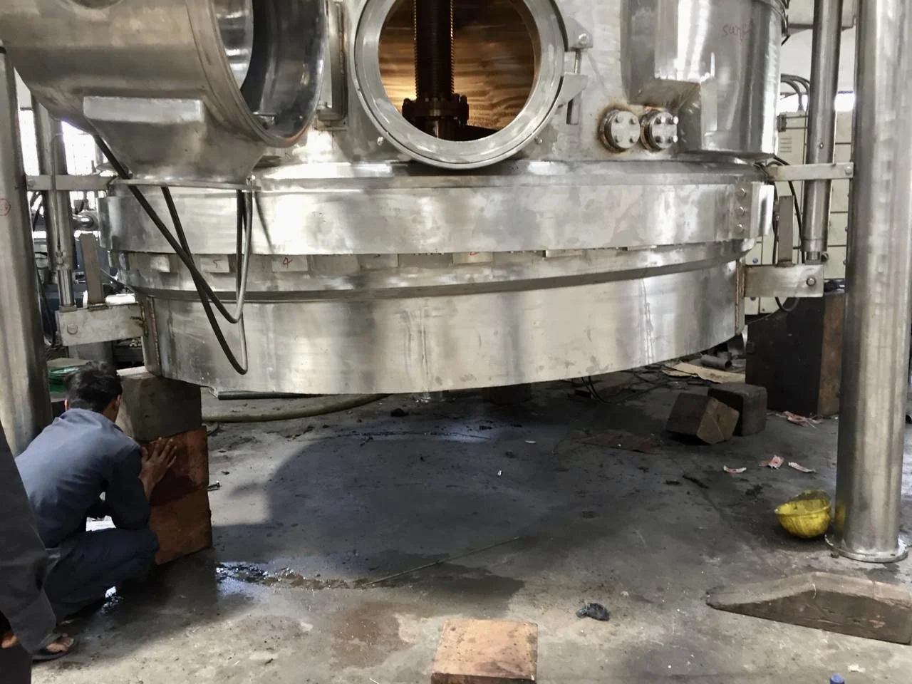
Photograph provided by a client while assembling the equipment. Here unguided freeload is seen tilted. Note, piston rod of hydraulic cylinder on the left has extended more compared with on the right - which hasn't left position. Here the freeload is under free-fall without adequate counter. See the video below and read on to understand how it can be handled.

Video of load testing of hydraulic cylinders synchronising on test rig made at Rajvivik Enterprise. Please note, video of the full stroke lowering and lifting is playing at 10X the working speed to avoid viewers snoozing (It’s seven minutes). If you are in to seeing details I have uploaded the original video. Link to view it - https://youtu.be/wL3xXurG_P0
What’s happening in the video.
(You can directly skip to the ‘Points to be noted’ part if you are not someone who likes to go deep into machines.)
1. When the flow from the pump is directed to rod end side of the cylinders, it passes through a set of gear motors connected mechanically to each other.
2. Suction or intake side, which is connected for all the pumps, receives the oil flow and rotates all the gears at the same speed since they are mechanically connected. This makes the flow output equal. for e.g. flow of pumps with equal volume rotating at same rpm is equal.
3. Equal flow reaches the rod end side of all cylinders connected upstream of flow divider and considering their annular area is equal they will lift at the same speed.
4. When the flow from the pump is directed to piston side of the cylinders, the flow coming out of the rod end side passes through a set of gear pumps connected to each other mechanically, before passing through a counter valve. Counter valve stops the load from free falling.
Points to be noted
1. If the start point of all the cylinders are not the same, the error will remain through the movement. It will not correct mid stroke.
2. If there is a physical obstruction on one side of the bottom, pressure on the upstream side in the power unit will increase. This makes back pressure on one of the gear and stress on the mechanical link with which the gear’s shafts are connected and can damage the flow divider. The flow divider will not compensate for flow to get the cylinders back to equal stroke once the obstruction is removed.
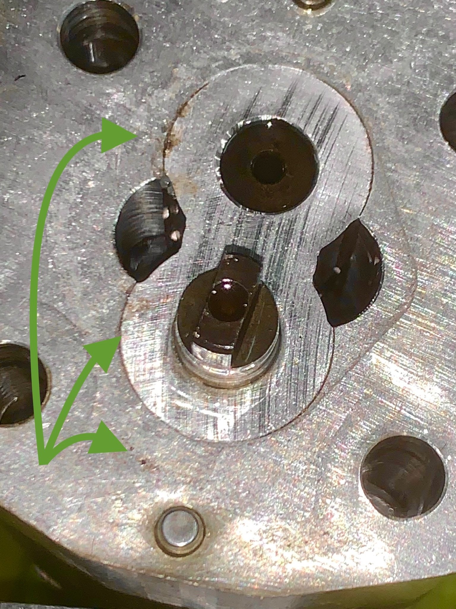
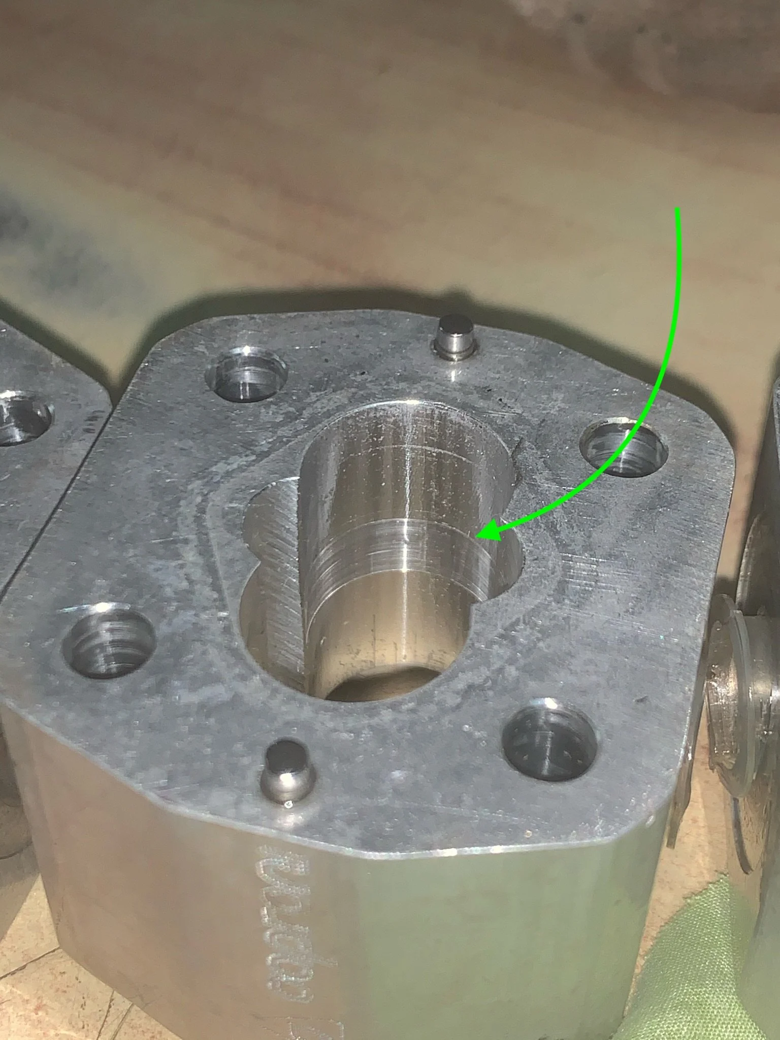
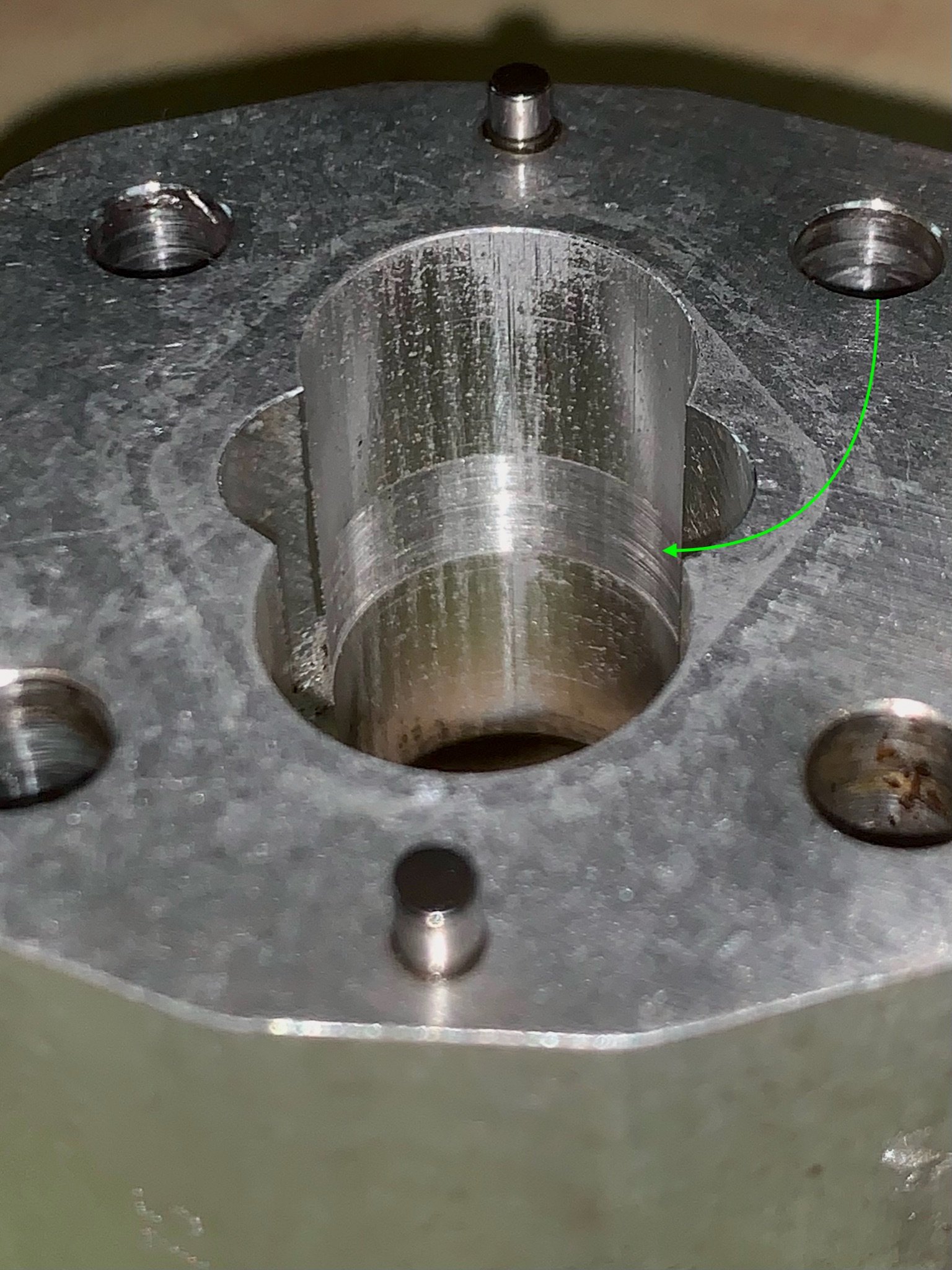
3. If there is contamination in the oil, volume of each gear pump may be modified by scouring resulting in unequal flow and out of sync stroke length. Refer photograph showing contamination inside flow-divider, slightly scoured inside surface of gear flow divider and heavily scoured surface if geared flow divider.
4. The counter balance valve has to be set to counter the weight of the load. If excess counter is given there will be back movement of piston rod with the down stroke ends. If the under counter is given there will be even or un-even free fall and stress on flow divider’s mechanical linkage. This may result in damaged flow divider.